


Views: 0 Author: Site Editor Publish Time: 2026-08-07 Origin: Site


Specifying the correct tolerances in outsourced manufacturing is a constant balancing act. It serves as the critical link between product functionality and manufacturing scalability. OEM procurement teams face this demanding reality every single day. Ambiguous or overly strict limits cause massive production bottlenecks. They directly lead to inflated quotes and severely delayed lead times. Over-tolerancing also results in unacceptably high scrap rates. You need a reliable method to communicate your exact design intent. This helps you avoid paying for unnecessary machine time. This article provides OEM procurement and engineering teams with a clear guide. We offer a vendor-neutral framework for specifying and evaluating limits. You will learn to standardize tolerances across all outsourced manufacturing projects. We will cover the hidden costs of poor drawing specifications. You will also discover how to vet potential manufacturing partners confidently. Let us dive into the core principles of accurate dimensioning.
Default title block tolerances can unnecessarily inflate high-volume production costs by up to 300%.
Strategic application of GD&T (Geometric Dimensioning and Tolerancing) ensures parts mate correctly without requiring universally tight tolerances.
Evaluating a partner for precision CNC machining requires verifying their specific inspection equipment (e.g., CMMs) and quality compliance (e.g., ISO 9001, AS9100).
A complete RFQ must define material behaviors, critical-to-function features, and acceptable inspection methodologies alongside standard dimensional limits.
Machinists frequently encounter over-dimensioned parts on the shop floor. Specifying ±0.001" on non-critical features creates significant manufacturing hurdles. It requires much slower feed rates during production. Operators must execute frequent tool changes to maintain sharp edges. They also need specialized setups to prevent part deflection. This drives up cycle times rapidly.
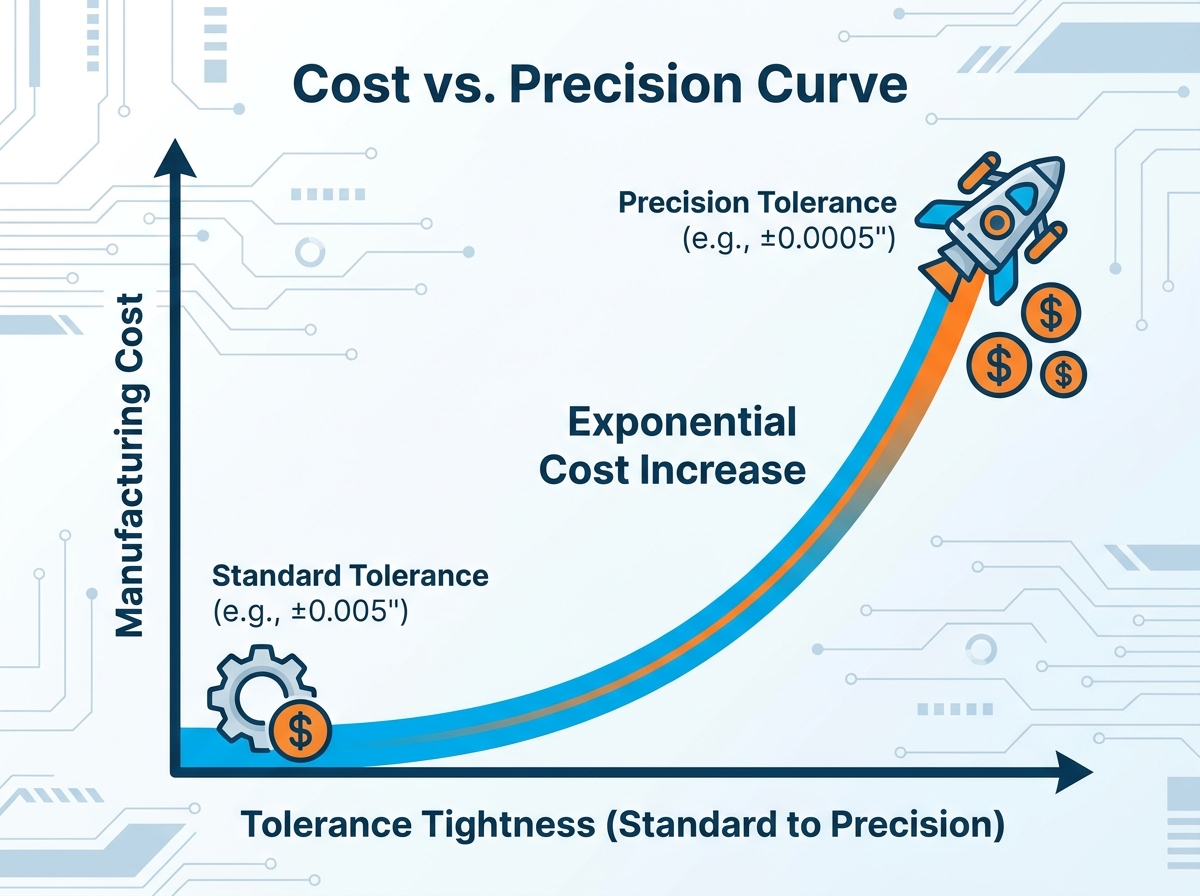
Tightening tolerance bands impacts your unit costs exponentially. A standard dimension requires normal operational speeds. Pushing this boundary to ±0.001" often doubles your price. Demanding ±0.0005" limits can easily quadruple it. You are paying for extended machine time and higher scrap risks. You also pay for intensive metrology labor.
Cost vs. Precision Curve Chart
Tolerance Band (Inches) | Machining Approach | Relative Cost Multiplier | Common Application |
|---|---|---|---|
±0.010" | Standard roughing and finishing | 1.0x (Baseline) | Non-mating external dimensions |
±0.005" | Standard finishing passes | 1.2x | Standard brackets, enclosures |
±0.001" | Slower feeds, rigid setups | 2.0x - 2.5x | Press fits, locating pins |
±0.0005" | Climate control, frequent tool swaps | 4.0x+ | Aerospace bearings, medical implants |
Standard CNC Machining capabilities generally align with ISO 2768-m. This widely accepted standard provides a reliable baseline of ±0.005” (0.125mm). Most modern machines achieve this repeatedly. However, certain applications demand much stricter control. You need true Precision cnc machining for highly specialized components. Aerospace bearings and medical implants are prime examples. They often require limits tighter than ±0.0005” to function properly.
Many buyers submit CAD files containing rigid default title block limits. These defaults rarely match the specific part's real-world application. This is a very common mistake in OEM procurement. A drawing might specify ±0.001" for every feature by default. This forces the shop to inspect every single hole and edge. Always review your title block notes before hitting send. Update them to reflect the actual functional requirements.
Different features require entirely different specification approaches. You must understand when to apply standard rules versus custom limits.
Industry standards like ISO 2768 save engineering time. They provide baseline expectations for non-critical features. You simply reference the standard in your drawing notes. Custom limits apply only when parts mate or move. Use them sparingly to control specific functional interfaces.
You can communicate custom boundaries in three primary ways. Each method serves a specific engineering purpose.
Limit Tolerances: Display the absolute maximum and minimum acceptable sizes. The machinist simply measures to ensure the part falls between them.
Bilateral Tolerances: Allow variance equally in both directions from a nominal size (e.g., 1.000" ±0.005").
Unilateral Tolerances: Shift the entire acceptable variance to one side (e.g., 1.000" +0.005" / -0.000"). You typically use unilateral limits for tight press fits.
Geometric Dimensioning and Tolerancing surpasses simple linear methods. It controls the shape, orientation, and location of critical features. Complex OEM components need GD&T to guarantee assembly fit. It prevents driving up machine time needlessly.
Core GD&T callouts include:
Flatness: Ensures a sealing surface remains perfectly level.
Concentricity: Keeps multiple diameters aligned along a central axis.
True Position: Defines the exact allowable location of a hole. It provides a circular tolerance zone instead of a restrictive square one.
Different materials behave differently during the cutting process. Your dimensional limits must account for these base properties. Plastics exhibit high thermal expansion. They warp easily during aggressive milling. Titanium offers high rigidity but builds up localized heat. You must assign looser limits to soft plastics than to rigid metals.
Material Behavior Matrix
Material Type | Machining Characteristics | Recommended Baseline Tolerance |
|---|---|---|
Aluminum (6061) | Highly stable, dissipates heat well | ±0.005" |
Stainless Steel (304) | Work hardens, requires rigid tooling | ±0.005" |
Acetal/Delrin | Stable for a plastic, moderate expansion | ±0.008" |
Nylon | Absorbs moisture, expands significantly | ±0.015" |
A supplier's promise means very little without verifiable proof. You must evaluate their physical capabilities and quality systems.
Modern machine shop upgrades directly translate to repeatable accuracy. 5-axis mills allow complex parts to be completed in one setup. Fewer setups mean fewer opportunities for human error. Thermal compensation systems monitor machine spindle temperatures constantly. They adjust the cutting path to account for thermal growth. High-pressure coolant clears chips efficiently to maintain precise cutting conditions.
A shop's dimensional claims rely entirely on their measurement capabilities. You should actively look for advanced metrology equipment. In-house Coordinate Measuring Machines (CMM) are non-negotiable for aerospace or medical work. Optical comparators verify complex external profiles quickly. Laser scanning systems provide comprehensive secondary validation for complex geometries. Ask for a list of their calibrated metrology equipment.
Robust documentation proves a shop can sustain accuracy over time. Require First Article Inspection (FAI) reports before approving high-volume runs. FAI reports verify every single dimension on the drawing.
You also need assurance for long-term production. Request Process Capability indexes like Cp and Cpk. A Cpk score of 1.33 or higher indicates excellent statistical control. It proves the shop can hold your limits across thousands of units.
Optimizing your design before requesting quotes saves tremendous capital. DFM principles help you isolate what truly matters.
Isolate your Critical-to-Quality features early in the design phase. Usually, only 10% to 20% of part features actually dictate performance. These include bearing journals, O-ring grooves, and mating pin holes. You should apply strict controls only to these specific areas. The remaining features can follow standard shop rules.
Deep pockets make holding tight sizes difficult. Standard end mills experience tool deflection when reaching too far. A Length-to-Diameter (L:D) ratio exceeding 4:1 causes vibration and chatter. This increases scrap rates and expense dramatically. Keep complex features accessible. Use larger corner radii to allow thicker, more rigid tools.
Roughness average (Ra) is entirely distinct from dimensional boundaries. A very tight size limit might still yield a rough surface. Conversely, a smooth mirror finish does not guarantee dimensional accuracy. Ensure both requirements align without conflicting. You must also account for secondary treatments. Anodizing and plating add measurable thickness to the final part. Always specify whether dimensions apply pre-plating or post-plating.
A thorough Request for Quote (RFQ) eliminates costly guesswork. You must provide comprehensive data to receive accurate pricing.
Missing information always leads to conservative, inflated quoting. Ensure your RFQ packages contain these essential elements:
Fully dimensioned 2D PDF drawings. CAD models alone do not convey specific tolerances or threaded hole data.
Clearly marked critical dimensions. Highlight the CTQ features for prioritized inspection.
Material grade and temper details. Specify the exact alloy condition required (e.g., 6061-T6).
Post-processing finish requirements. Detail any masking requirements for anodizing or powder coating.
You should interview potential suppliers using targeted, technical questions. This reveals their true engineering depth.
"What is your standard shop tolerance if none is specified?" This establishes their baseline capability and default ISO compliance.
"How do you handle tolerance stack-up analysis during the DFM phase?" Good partners proactively review your assembly for stacked errors.
"What is your protocol if a critical dimension falls out of tolerance during a high-volume run?" Look for documented isolation and root-cause analysis procedures.
"Do you perform CMM inspections in a climate-controlled room?" Temperature fluctuations ruin micro-inch measurements.
Specifying the correct tolerances in CNC manufacturing requires strategic thinking. You must balance functional requirements against production costs. Specify tightly only where absolutely necessary for assembly performance. Rely on GD&T for complex fits instead of blanket linear rules. Most importantly, partner with shops capable of transparently validating their accuracy.
Take action today to improve your procurement outcomes. Review your current drawing templates and remove overly strict title block defaults. Download a standardized RFQ template to ensure consistent quoting. Submit your most challenging 2D drawing to a qualified vendor for a comprehensive DFM review.
A: The generally accepted baseline is ±0.005" (0.125mm) for standard metals. This aligns with ISO 2768-m specifications. Most commercial equipment holds this reliably. However, specialized precision shops can routinely achieve much tighter limits, often reaching ±0.0005" or better when utilizing climate control and 5-axis machinery.
A: Surface treatments add physical material to the part. Standard Type II anodizing typically adds up to 0.001" per surface. You must specify whether your dimensional limits apply "pre-plating" or "post-plating." Failing to do so causes perfectly machined parts to fail final inspection after the finishing process.
A: No. CNC routers excel at cutting large, flat sheet materials quickly. They typically hold limits around ±0.010" to ±0.015". Rigid CNC mills handle thicker, harder materials and can easily maintain ±0.005" or tighter. Always manage your expectations based on the equipment type used.
A: Tightening to ±0.001" forces the machinist to slow down significantly. They must take multiple light finishing passes. It increases the risk of scrapped parts. It also demands frequent tool replacements and requires advanced CMM inspection time. You are essentially paying for increased labor, tooling, and risk mitigation.


